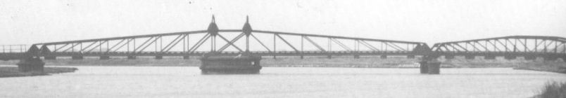
The original bridge was replaced soon after 1906 after the decision to convert to standard gauge. The bridge was rarely opened other than for annual maintenance purposes. The swinging span was 146ft long and the fixed span 73ft 6ins. The bridge was disabled by the Army during WWII, the piles still support the footbridge in this position.
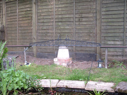
The swinging span would be about 2.3m long if true to scale, my model is a mere 1.8 long to keep material costs down (the steel came in 6m lengths). Though it's near the garden pond I've decided to keep the bridge away from the water. The oil that drips from a live steam loco probably won't do the pond life any good and I don't want my trains taking swimming lessons!
I spent some time with the relevant photos in Branch Line To Southwold, using digital callipers to measure the significant dimensions available from the pictures. These were collated in a spreadsheet and the dimensions of my model calculated. Struggling to remember my trigonometry from school I calculated the angles that needed to be made in the top beam of the truss and prepared card templates for the V cut and final angle.
I initially considered brass or aluminium for the construction of my bridge but was put off by the cost, looking at my local DIY store the cost of steel section was expensive too but a call to a steel wholesaler in the south of Suffolk got me a much better price. The main beams of the sde trusses are from 12mm by 12mm by 3mm thich steel angle, two at the bottom, one over the top. The uprights and diagonals in the trusses, the diagonals in the floor and the beams supporting the rails are 10mm by 3mm. The major cross members are 12mm by 12mm, other cross members 6mm by 6mm. The hoops over the top of the centre sesction are again 6mm by 6mm.
The solid sections at the end of each truss, the kite shaped pieces supporting the hoops and the plates connection the floor diagonals are all 1.6mm thick plate. It's all held together by 6BA nuts and bolts of differring lengths.
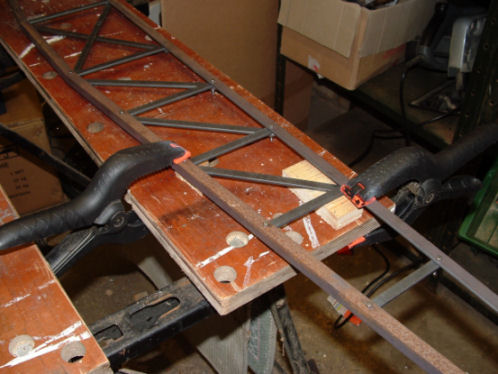
The steel angle that forms the top and bottom of the side trusses is a blue grey colour, I was advised that this type of steel can be brittle so I heated the areas I needed to bend with a small blow torch. Having bent both top beams I cut the bottom beams to length and connected these together using the metal plates at each end. The two uprights either side of the centre section were the next to go in, followed by the cross beams that then held things all square.
The positions for the diminishing uprights on each side were then measured, marked, centre punched and drilled through. An engineers square was used to mark the positions on the top beam and holes produced there too. Finally the uprights were cut, drilled and bolted. Once all the uprights were in place I started back at the centre and worked to each end putting in the diagonal pieces. Finally the lower beam was removed and offered up to a third beam. The holes were drilled through and the truss was bolted together for the final time.
Repeating all this for the second truss I then started to think about the floor of the bridge. 4 lengths were cut from some 12mm by 12mm steel and these were fitted in line with the ends and middle two uprights of each side truss, lengths of 6mm by 6mm steel were then bolted under the other uprights.
The original bridge has diagonal cross members keeping the floor square, but I felt the displacement caused by two bars crossing would make the trackbed undulate so I went for a zigzag pattern instead. Small plates were attached above every other cross bar and the diagonals bolted under these. Finally two lengths of the 10mm by 3mm strip were fixed approximately 40mm apart down the centre of the floor and fixed with countersunk bolts, these will directly support the track. The bridge was then turned over and the bolts all trimmed back so they don't look unsightly.
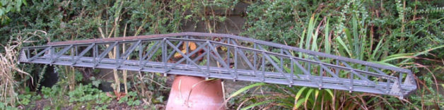
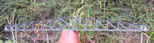
An outstanding feature of the original bridge are the two hoops at the centre section, these proved quite a challenge to replicate, probably due to my less than fine engineering!
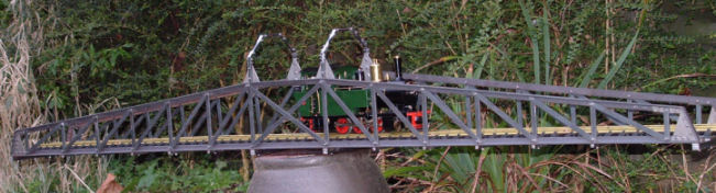
Three tins of car spray paint later it's finished and ready for the garden.
Having cleared the plants, cast a central support and built the track bed between the decking and Walberswick, the bridge is now in position.